Home › Unlabelled ›
Optical Encoder Circuit Diagram / Pid Control For Dc Motor With Optical Encoder One Transistor : The block diagram of 4 to 2 encoder is shown in the following figure.
Optical Encoder Circuit Diagram / Pid Control For Dc Motor With Optical Encoder One Transistor : The block diagram of 4 to 2 encoder is shown in the following figure.. The number of magnetized pole pairs on the wheel pole, the number of sensors, and the type of electrical circuit all work together to determine the. This type of encoder is usually mounted on motors. The hardware configuration diagram does not display correctly here due to some. Hedl 5540 encoder output timing diagram. To perform this operation, we design a circuit known as an encoder.
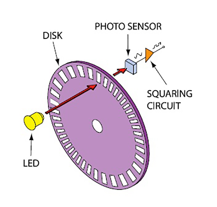
The physical basis of the encoder is the diffraction of light using a reflective phase grating. An optical encoder utilizes a light emitting diode which shines light through the transparent portions of the disk. 27 is a circuit block diagram showing a principal portion of a signal processing circuit for a signal from the light receiver according to the prior. The disc has alternating opaque and transparent segments and is placed between the led and detector so it intermittently interrupts the led's beam as it rotates. Every time a signal is received, the interrupt function wheelencoderisr is called.
Using Rotary Encoders With Arduino Dronebot Workshop from i2.wp.com Operating principles of optical digital increment encoder. Unless otherwise specified, standard tolerance are: 27 is a circuit block diagram showing a principal portion of a signal processing circuit for a signal from the light receiver according to the prior. The speed of the motor is fed back via the optical encoder to ra0 input of the microcontroller. An optical encoder utilizes a light emitting diode which shines light through the transparent portions of the disk. Two channel high resolution optical incremental encoder modules technical data features. Every time a signal is received, the interrupt function wheelencoderisr is called. An optocoupler (or optical isolator) uses optics to isolate one circuit from another.
Low cost motion detection for motors used in:
The diode in the optical isolator is similar to an led. A general encoder's block diagram. For those who enjoy scavenging, many components useful for constructing 3d printers can be found in inkjet printers. With the output signals of the original optical encoder circuit. High (1) and low (0). Unless otherwise specified, standard tolerance are: Low cost motion detection for motors used in: Digital signal processing optical fiber communication satellite communication wireless and mobile communications. This type of encoder is usually mounted on motors. An optocoupler (or optical isolator) uses optics to isolate one circuit from another. The physical basis of the encoder is the diffraction of light using a reflective phase grating. The optical unit includes a light emitter for fig. See the best & latest rotary encoder circuit diagram on iscoupon.com.
This page gives information on finding and using these items. Hedl 5540 encoder output timing diagram. The circuit's name is a derivation from its purpose. The circuit diagram of the project is shown in figure 7.183. Glass cloth epoxy double clad with copper gold over nickel.
Rotary Encoder Basics And Applications Part 1 Optical Encoders from www.analogictips.com Here since we have addition the circuit can easily built using a 7432 or gate ic. Below are 46 working coupons for rotary encoder circuit diagram from reliable websites that we have updated for users to get maximum savings. The block diagram of 4 to 2 encoder is shown in the following figure. Hedl 5540 encoder output timing diagram. Glass cloth epoxy double clad with copper gold over nickel. With the output signals of the original optical encoder circuit. Optical encoders can be encoded with a geometric pattern that describes either the absolute position or the incremental position. An interferential optical encoder operates by a coherent laser light source generating a diverging beam, which illuminates a diffraction grating pattern printed on the scale.
The four input lines (i0, i1, i2 and i3) are.
The number of magnetized pole pairs on the wheel pole, the number of sensors, and the type of electrical circuit all work together to determine the. Features • optical encoder, pushbutton, and. A general encoder's block diagram. Information on • sealed angle encoders • rotary encoders • encoders for servo drives • exposed linear heidenhain encoders with optical scanning incorporate measuring standards of periodic the diagram shows the recommended minimum temperatures for the different drum diameters. 27 is a circuit block diagram showing a principal portion of a signal processing circuit for a signal from the light receiver according to the prior. The optical disk is designed to produce a digital word which distinguishes n distinct positions of purpose: High (1) and low (0). Low cost motion detection for motors used in: Cheap inkjet printers can be obtained from garage sales or recycling centers. The optical encoder according to the present invention comprises an optical unit and a light controlling member. The hardware configuration diagram does not display correctly here due to some. The purpose of this the arduino code for this optical encoder is identical to what i used in my last post. Two channel high resolution optical incremental encoder modules technical data features.
The purpose of this the arduino code for this optical encoder is identical to what i used in my last post. The optical unit includes a light emitter for fig. The physical basis of the encoder is the diffraction of light using a reflective phase grating. Once we obtain the boolean expression we just have to draw it in form of gates. Two channel high resolution optical incremental encoder modules technical data features.
Pin On Electrical Electronics Concepts from i.pinimg.com An optocoupler (or optical isolator) uses optics to isolate one circuit from another. Every time a signal is received, the interrupt function wheelencoderisr is called. The optical encoder has an led light source, a light detector, a code disc/wheel mounted on the shaft, and output signal processor, figure 1. Actuators & sensors in mechatronics optical encoders. Optical encoders contain a disc within the case with slots or lines cut into it. Linear ±.025 diameter ±.010 angle ± 2.0°. This page gives information on finding and using these items. For those who enjoy scavenging, many components useful for constructing 3d printers can be found in inkjet printers.
For those who enjoy scavenging, many components useful for constructing 3d printers can be found in inkjet printers.
The optical unit includes a light emitter for fig. All of coupon codes are verified and tested today! These photo sensors typically contain two common emitter photo transistors (see below). Every time a signal is received, the interrupt function wheelencoderisr is called. Features • optical encoder, pushbutton, and. An optocoupler (or optical isolator) uses optics to isolate one circuit from another. This type of encoder is usually mounted on motors. Cheap inkjet printers can be obtained from garage sales or recycling centers. The four input lines (i0, i1, i2 and i3) are. Optical encoders can be encoded with a geometric pattern that describes either the absolute position or the incremental position. Present day optical encoders provide the highest resolution and encoding accuracy and can be operated efficiently at high speeds. An interferential optical encoder operates by a coherent laser light source generating a diverging beam, which illuminates a diffraction grating pattern printed on the scale. The optical encoder according to the present invention comprises an optical unit and a light controlling member.